RPR (Rag Pushing Robot)
No documentation was written about RPR until a few years after it was completed. Because of this, most of the documentation on this page is very general. This is general documentation not a tutorial. No wiring diagrams are provided.
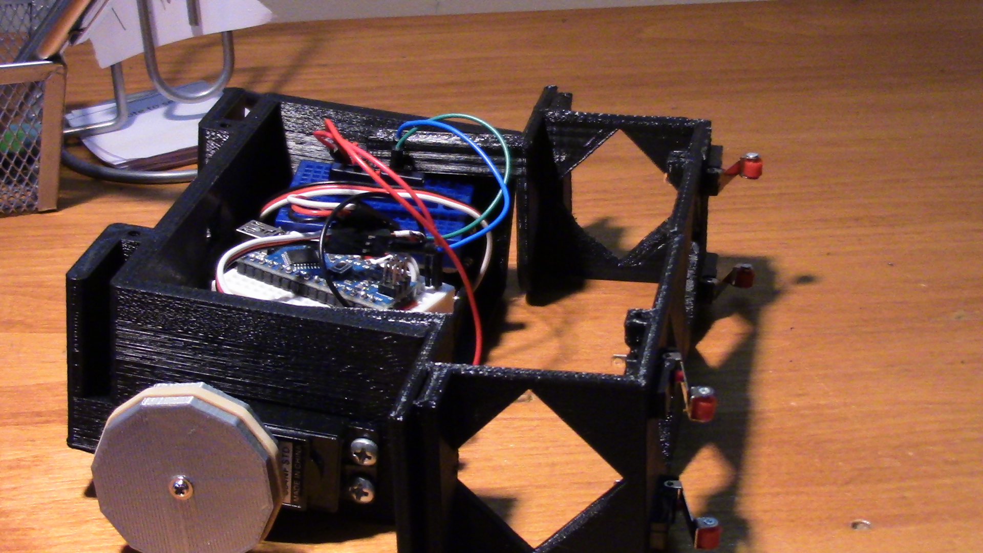
RPR is built around a central 3D printed part (download here.).
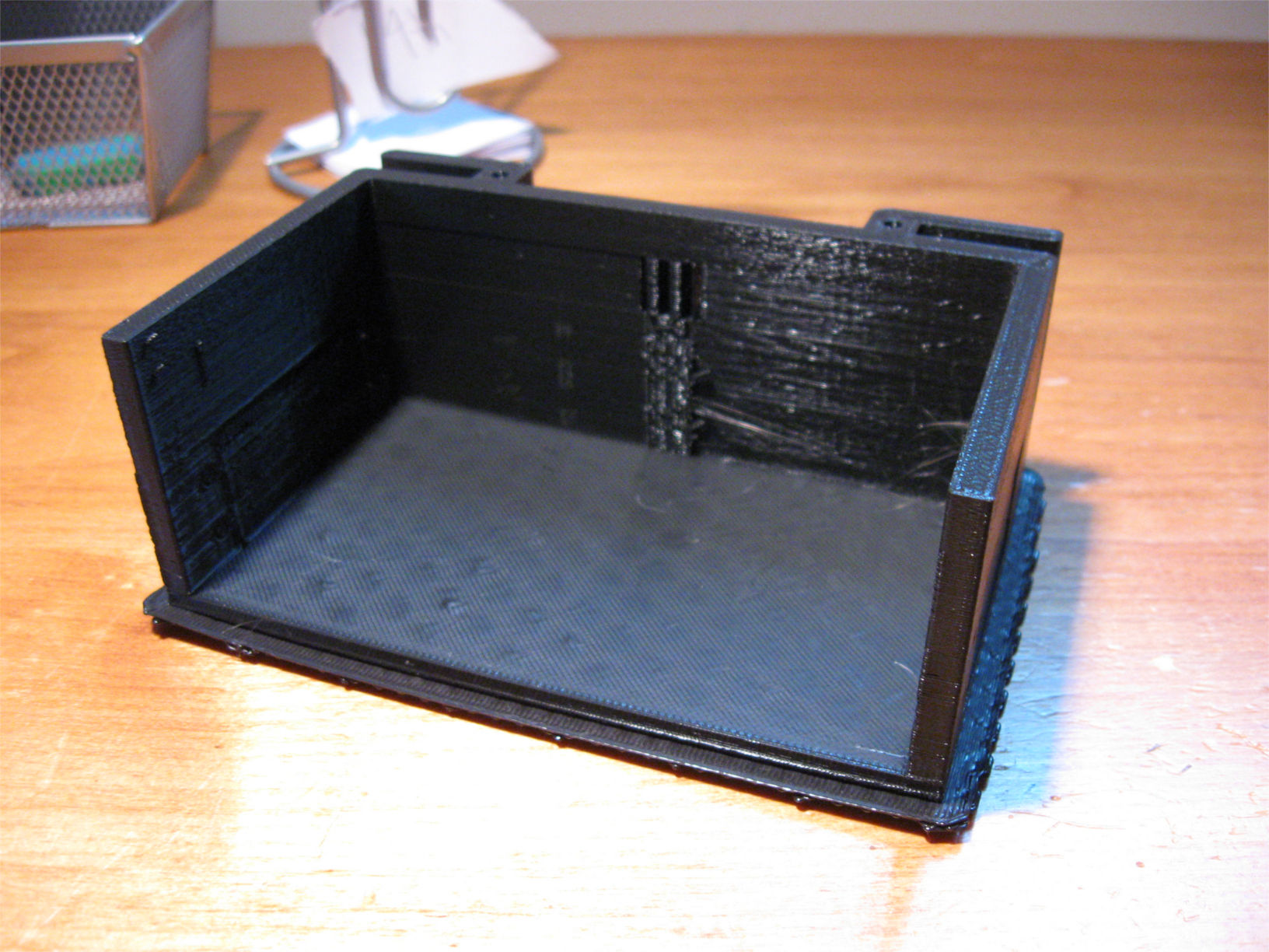
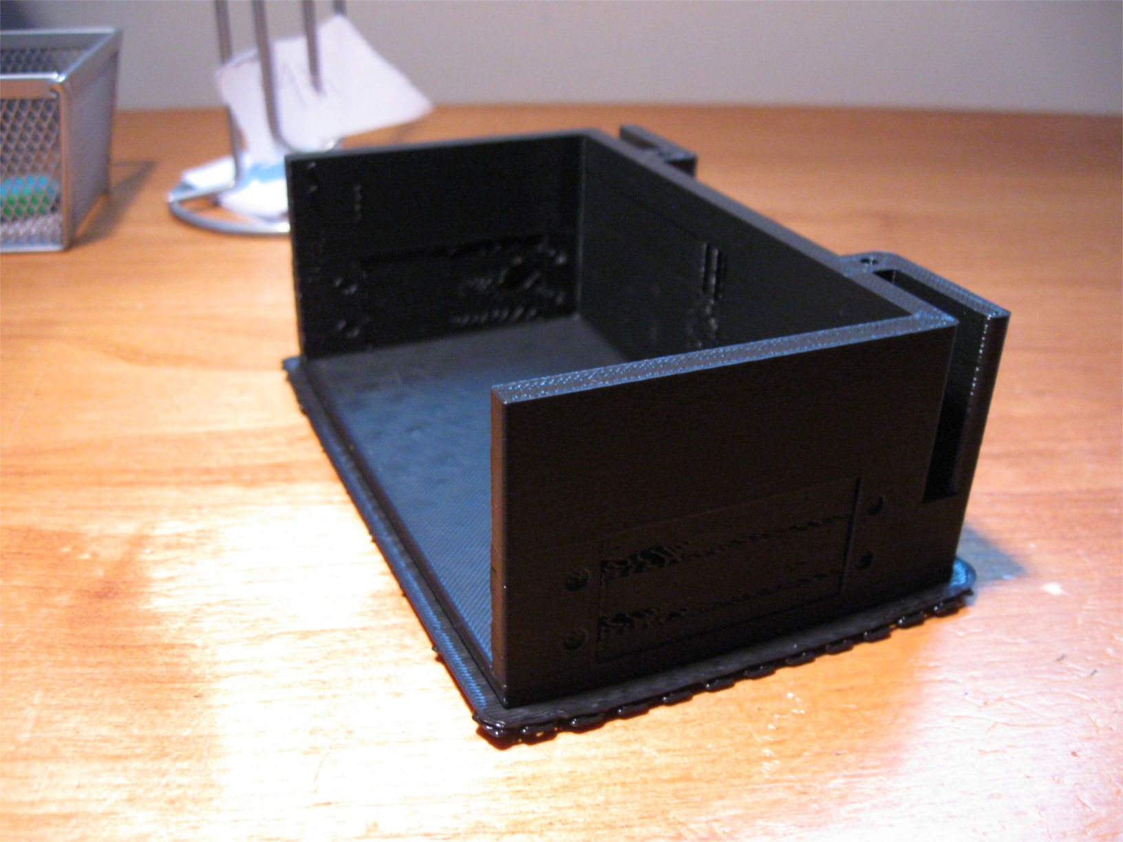
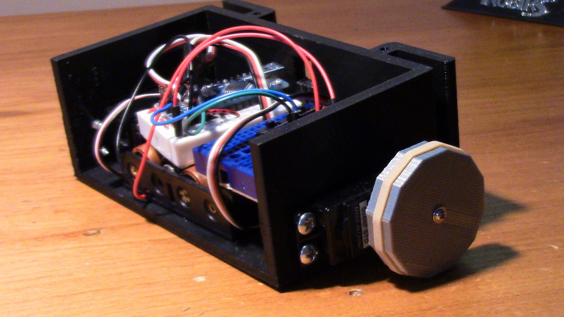
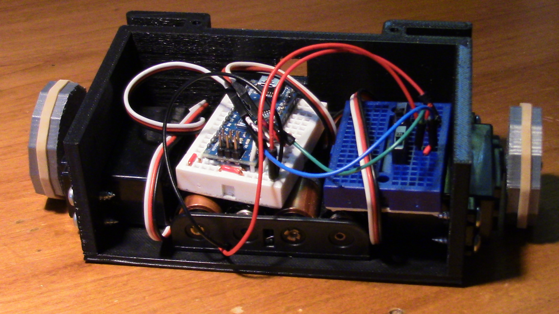
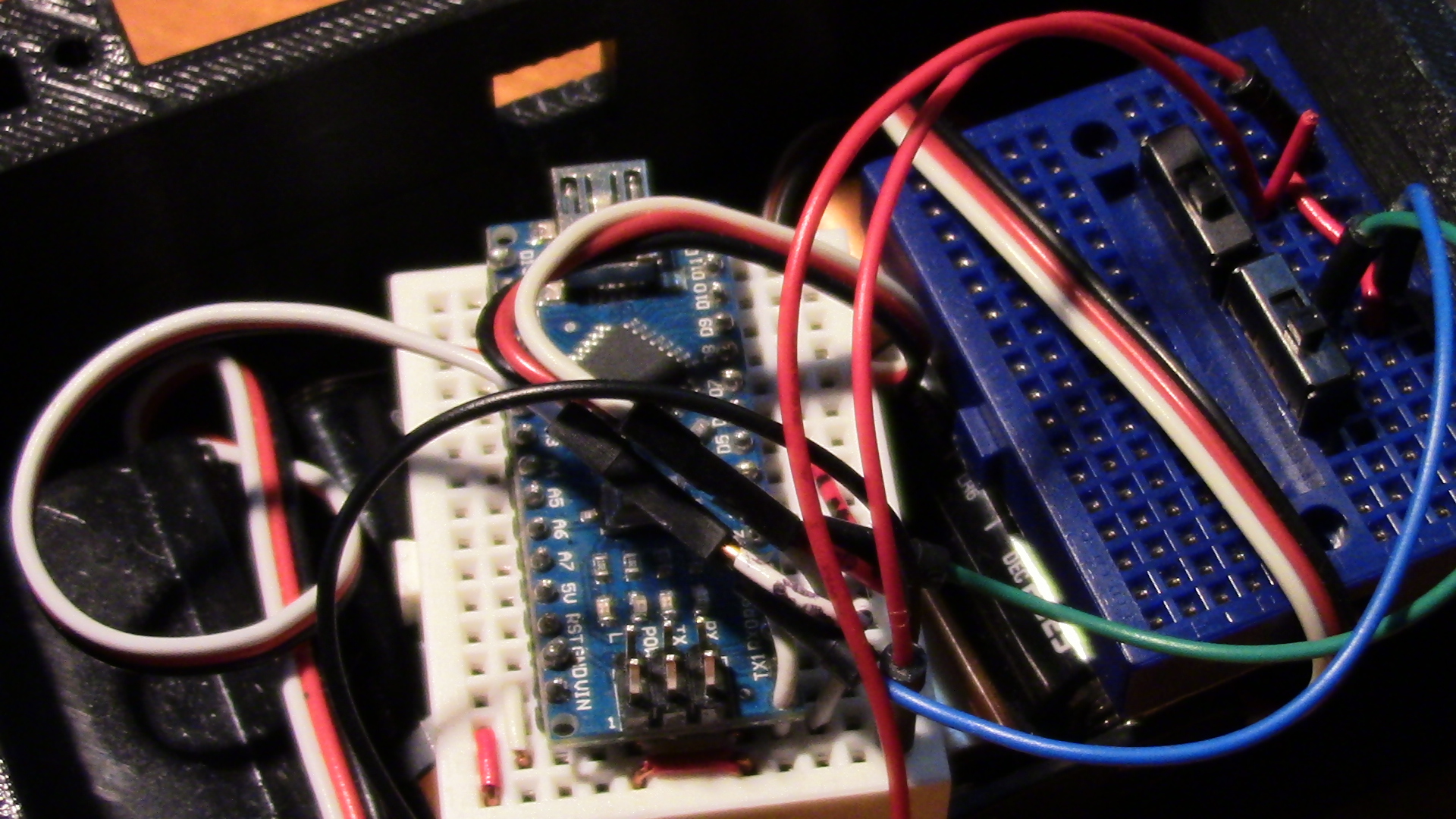
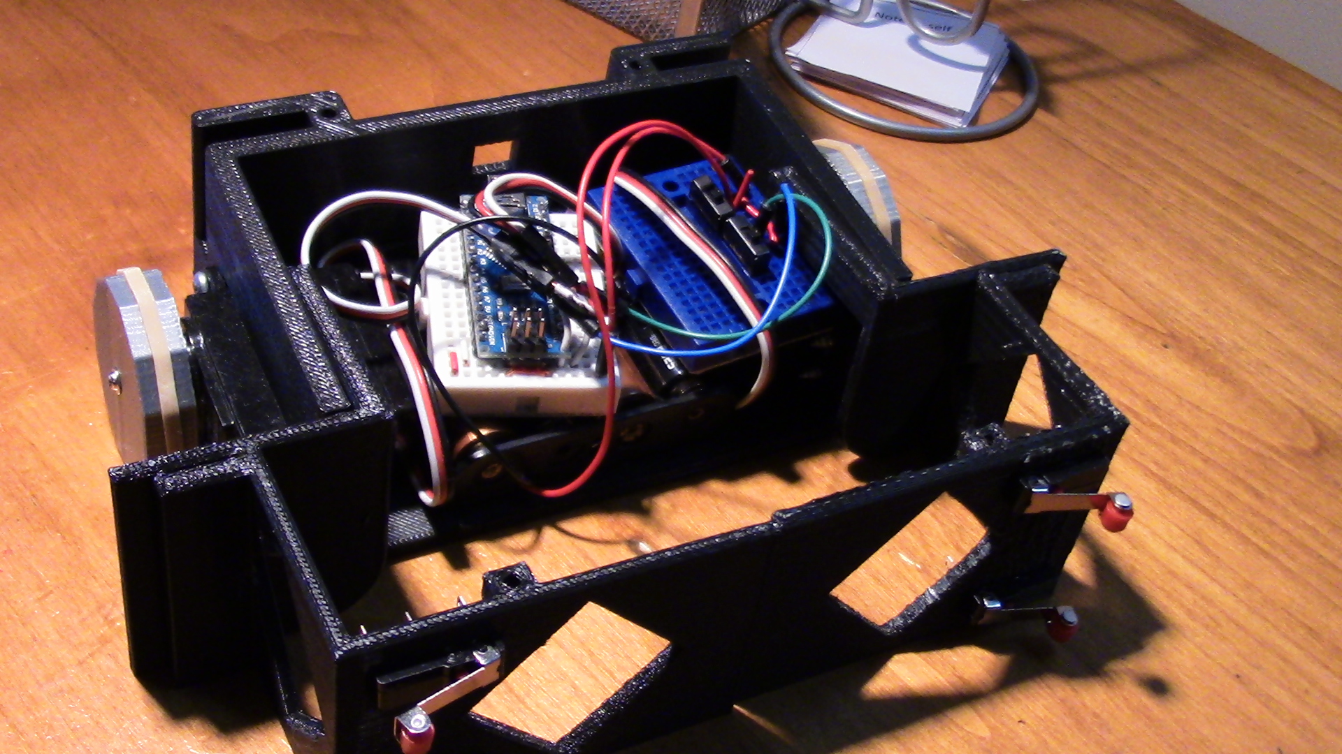
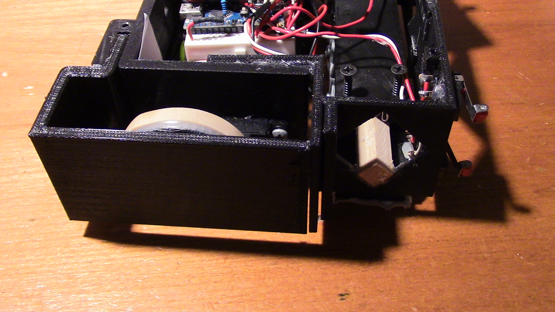
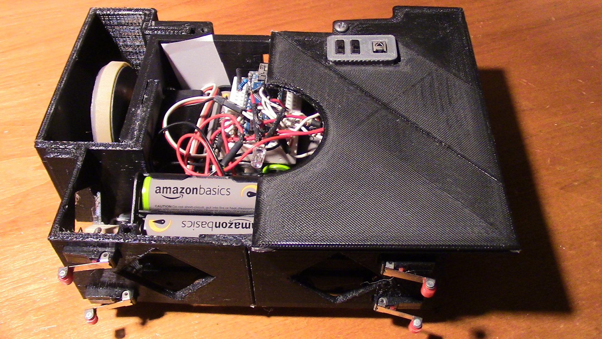
This part has space for a 4 AA battery holder, a mini bread board (the second blue bread board in the picture is for testing purposes only), and an Arduino Nano. The wheels are also 3D printed and can be downloaded here.
There is a square hole in the back of RPR that allows a USB cable to connect to the Arduino Nano. Some USB cables do not fit through this hole.
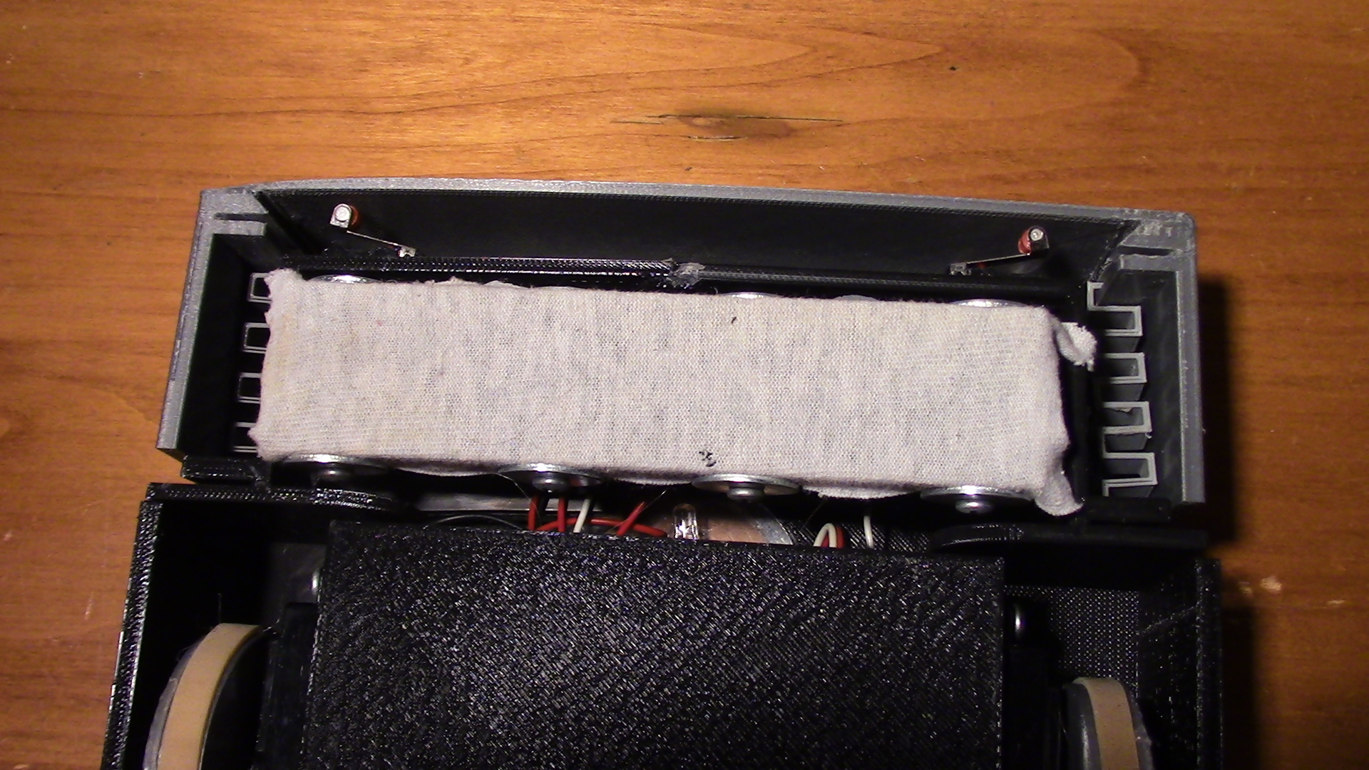
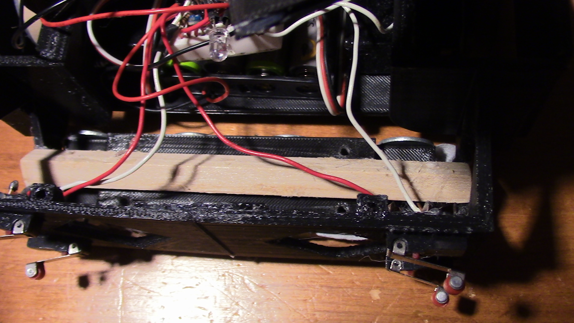
The front of RPR is made up of two halves in order to make it easier to print. The large diamond shapes are to save printing material. It holds 4 roller switches which connect to RPR's front bumper.
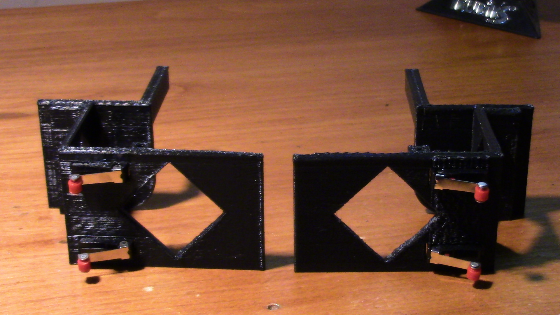
The front portions of RPR are intended to be affixed to the back portion with hot glue.
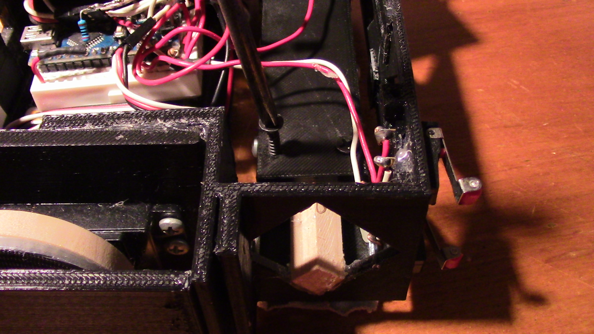
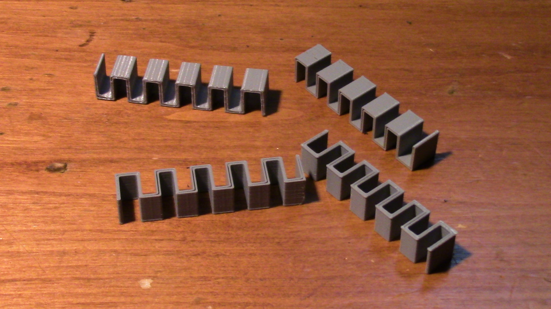
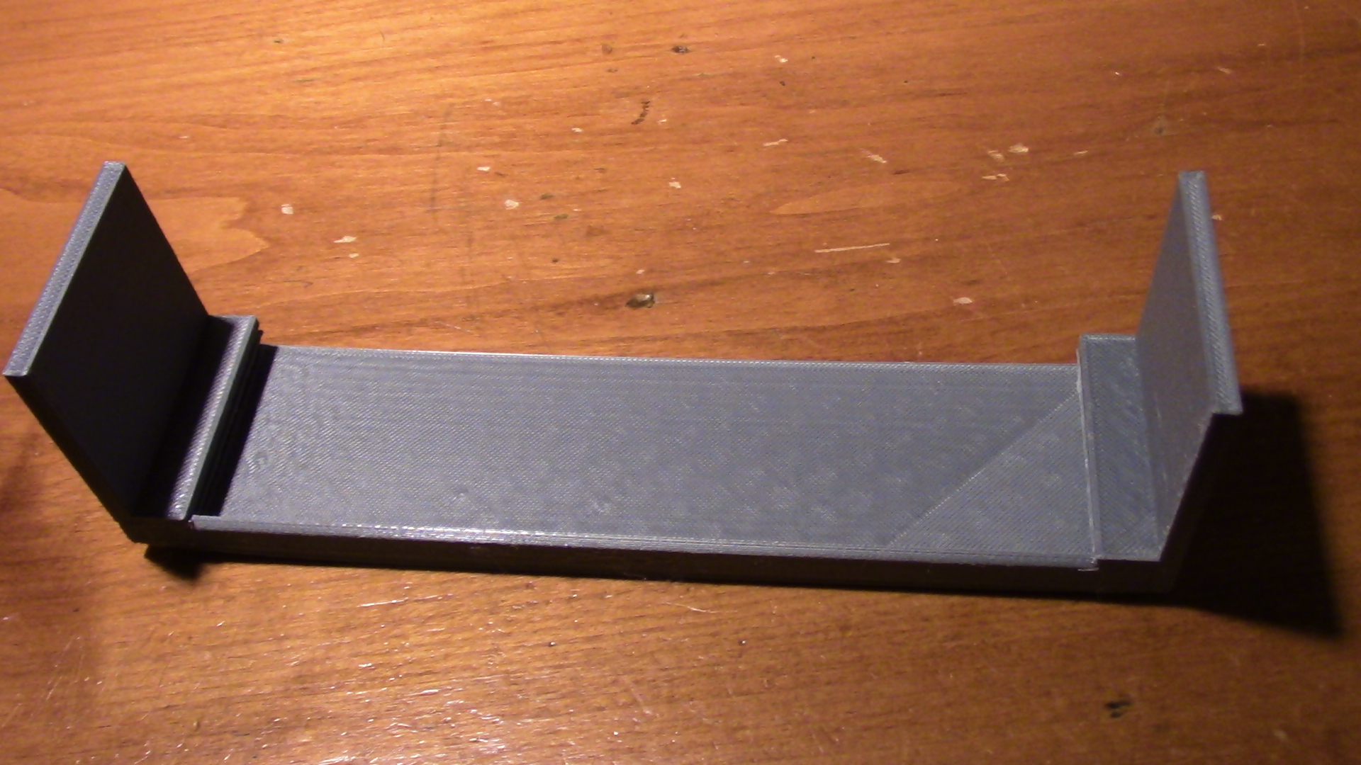
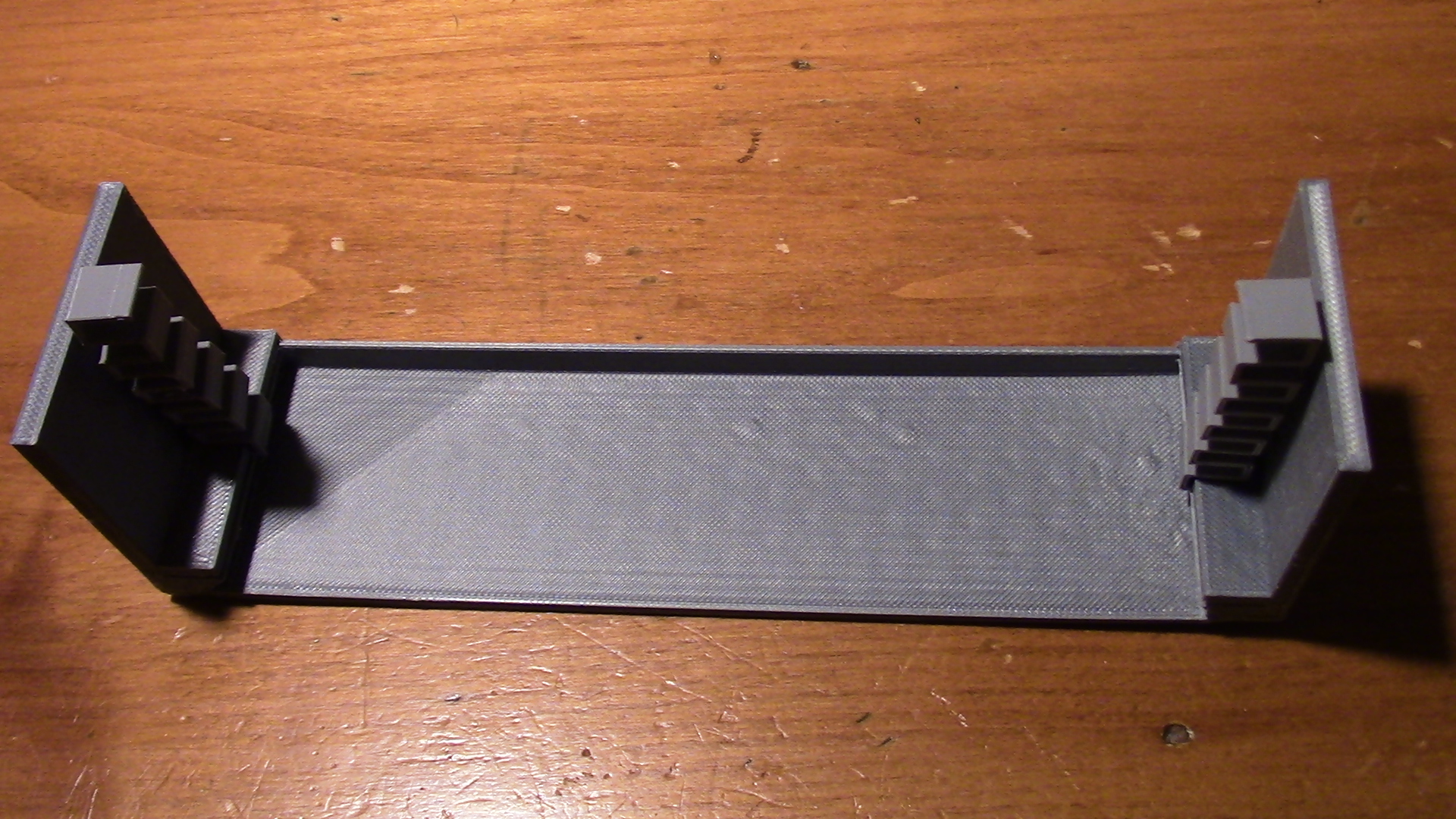
These two parts position the rag under the robot. The rag is affixed to this part with washers and 6x1/2 screws. The top half of this part can be downloaded here and the bottom can be downloaded here.
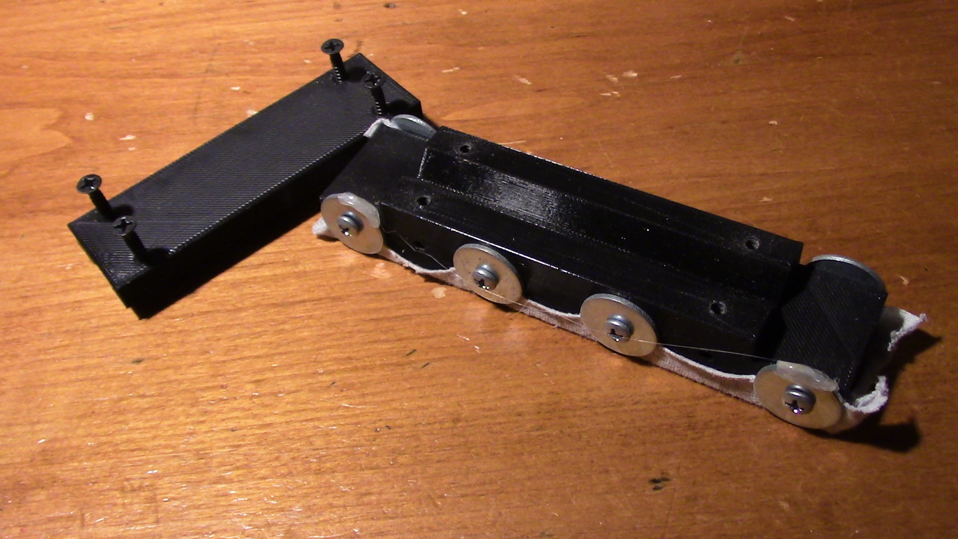
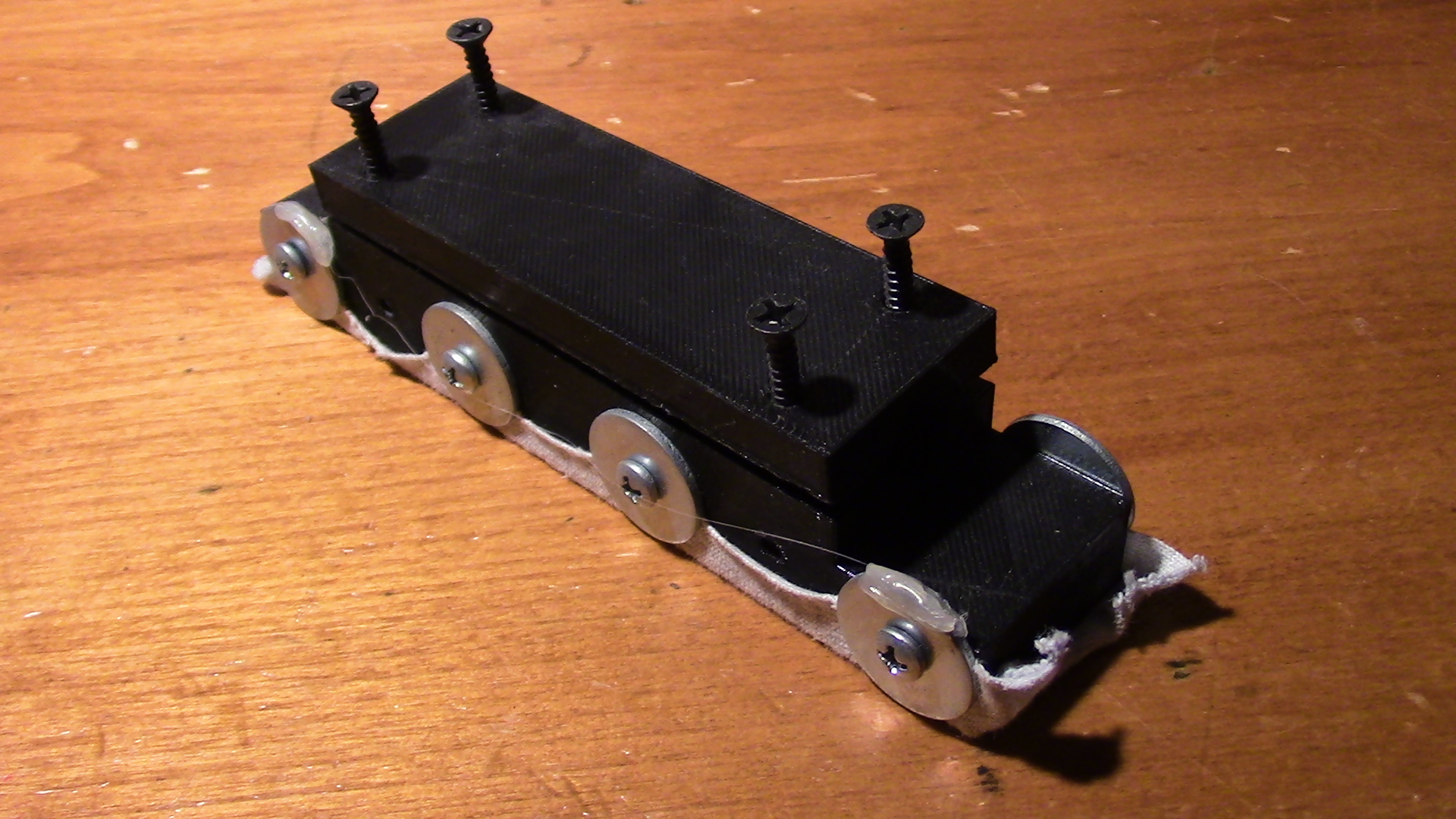
A length of 3/8" square wooden dowel is affixed to the front of RPR with hot glue.
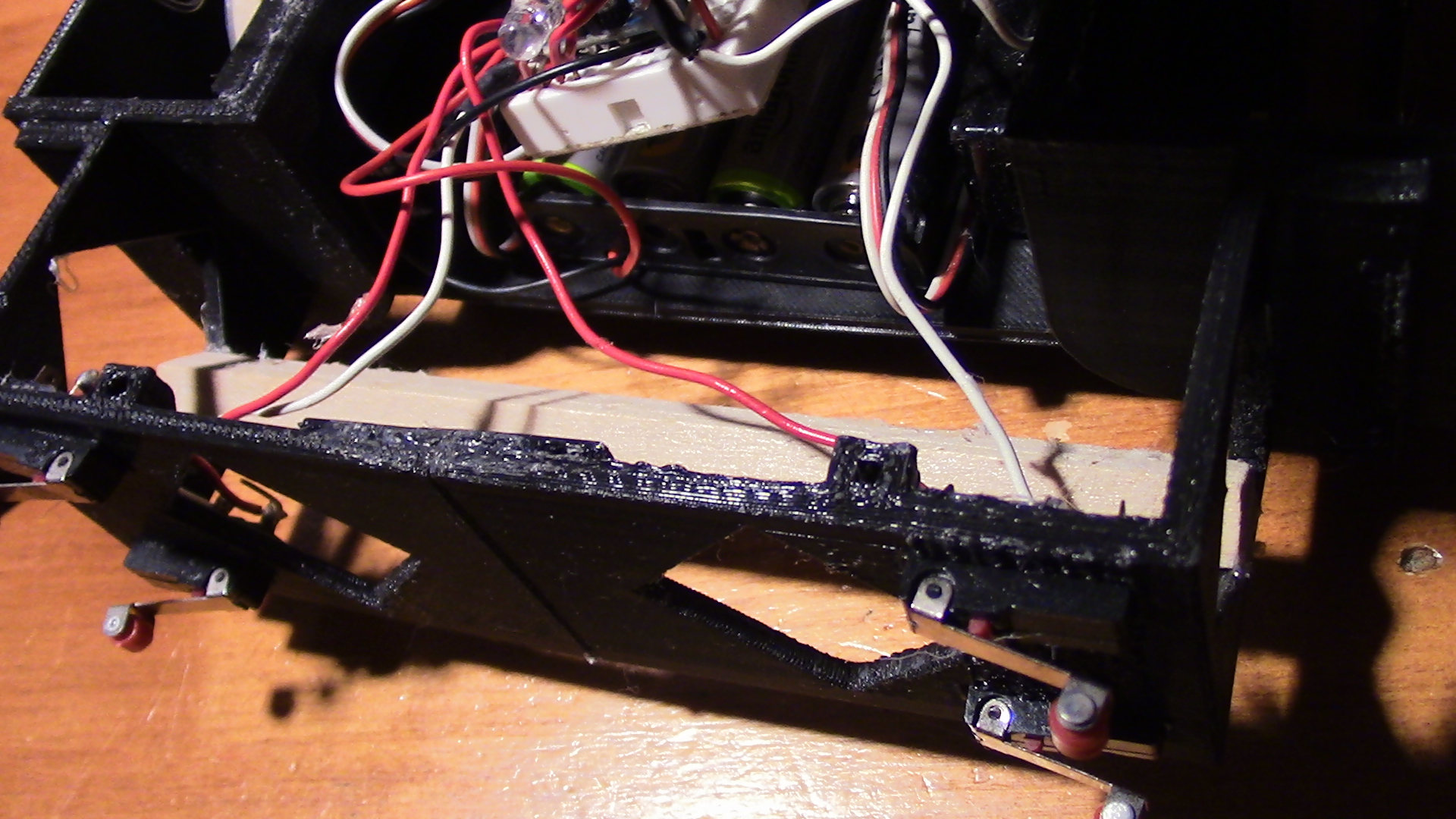
The 3D printed part that the rag is affixed to is clamped over the piece of wooden dowel.
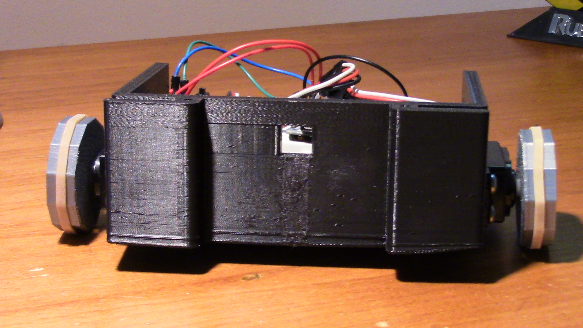
There are covers for both of the wheels. The right wheel cover can be downloaded here, and the left wheel cover can be downloaded here.

Both the right and left cover panels of RPR are 3D printed. Both panels are prone to warping while they are being printed. In order to counteract this, both panels are printed twice, once right side up and once upside down. These are then glued together face to face, so that each panel's warp can counteract the other's.
A 2 AA battery pack is placed in the front of RPR and wired in series with the 4 AA battery pack. This gives RPR 9V.
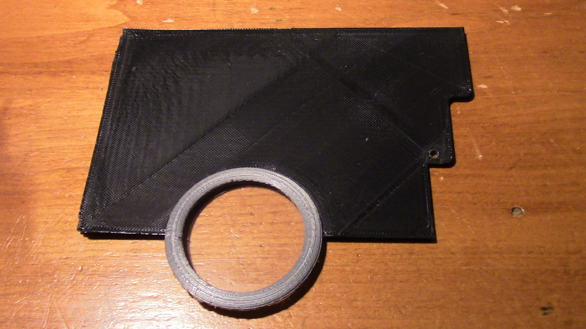
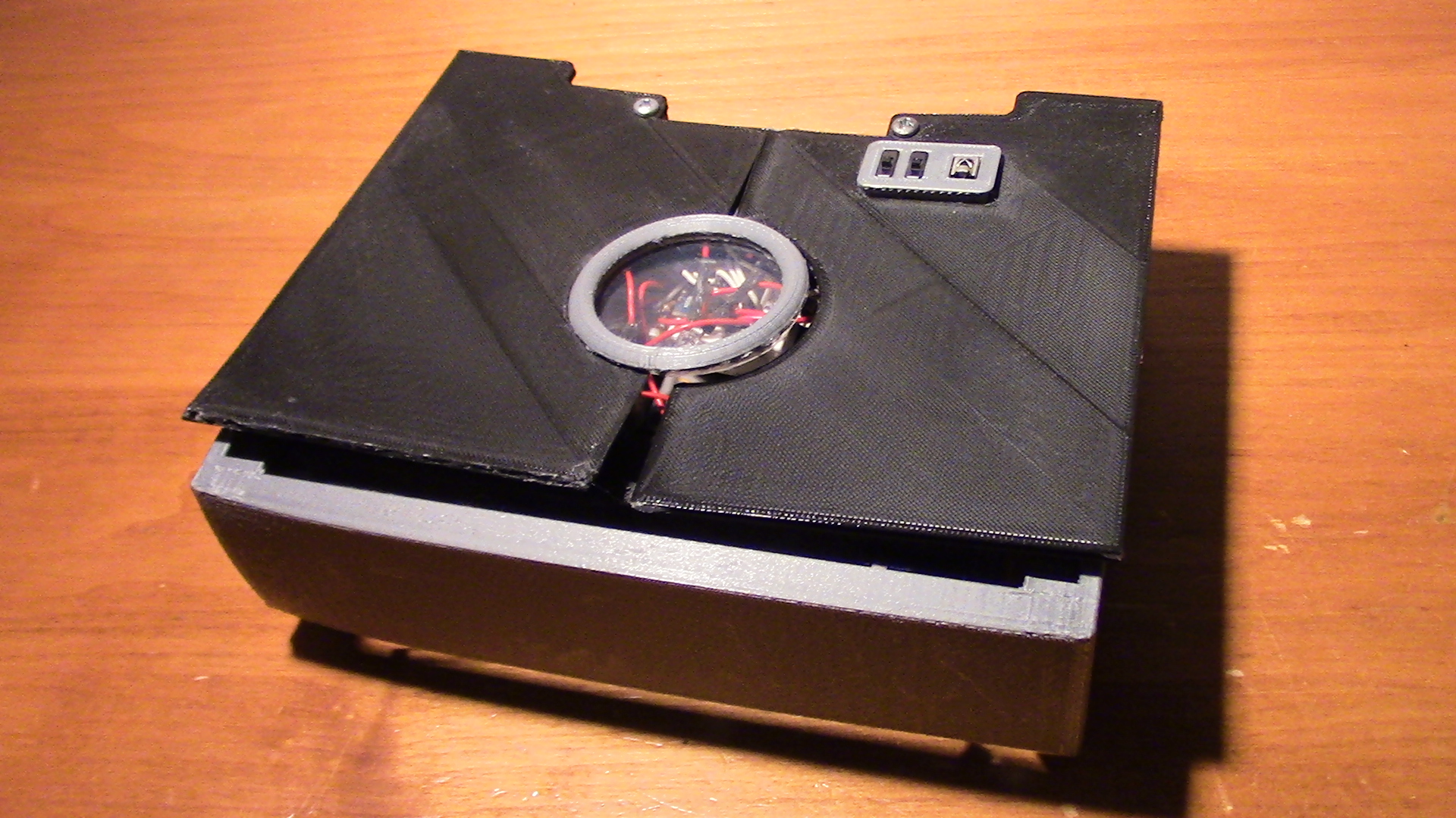
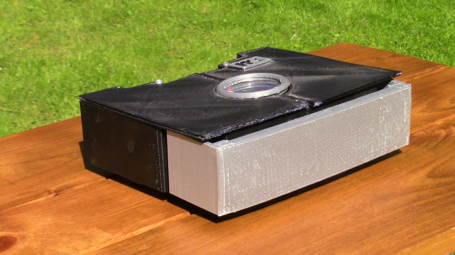
The center ring can be downloaded here.
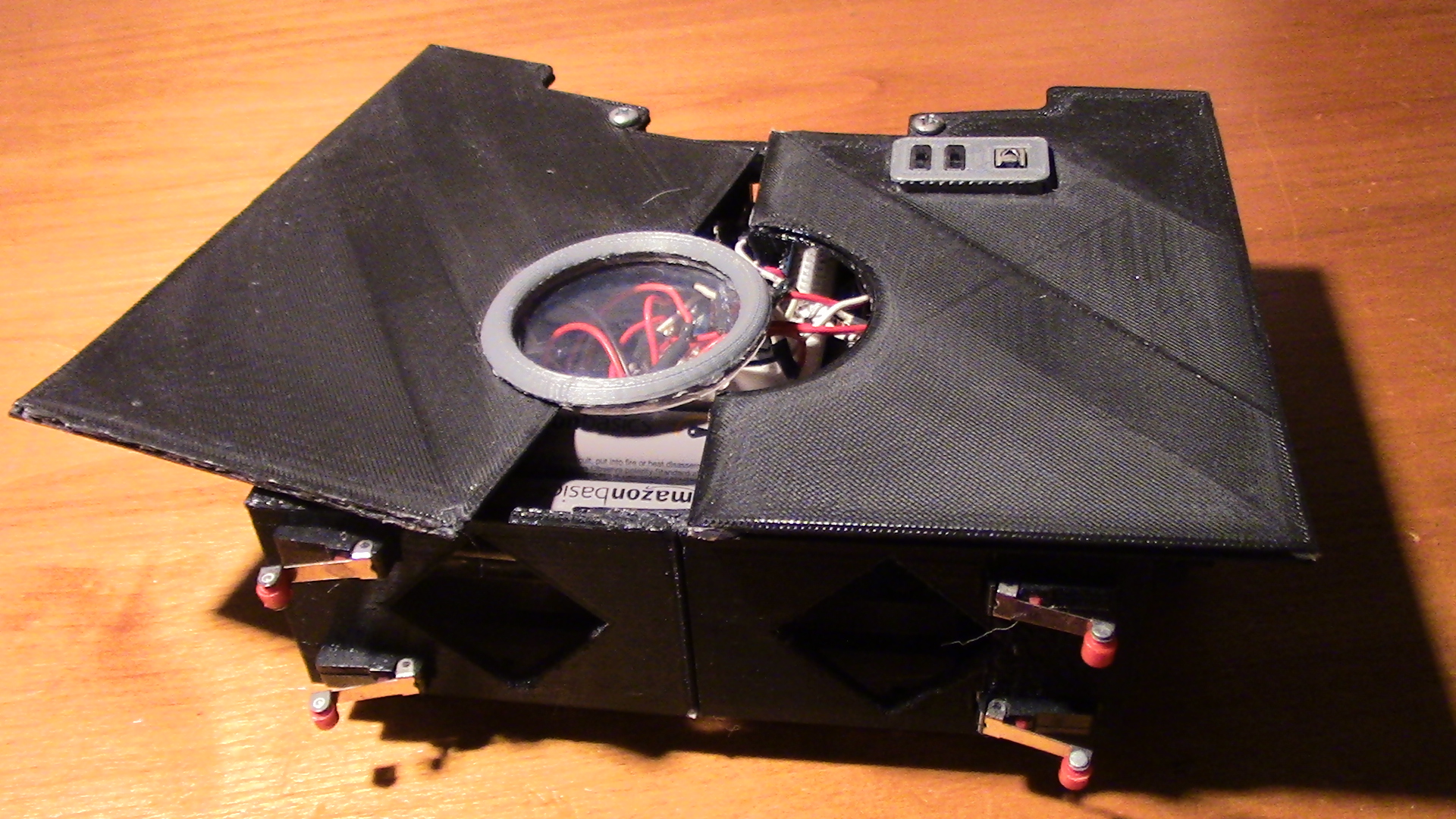
The switch panel can be downloaded here. It is intended to hold two switches and one IR receiver. It houses two switches so that power to the Arduino and motors can be controlled separately.

The front bumper is held in place by two 3D printed springs. The spring can be downloaded here.
The front bumper can be downloaded here
The springs slot onto the front bumper
The other end of the springs slot on to the rest of the assembly.